Pro Inductor Assembly
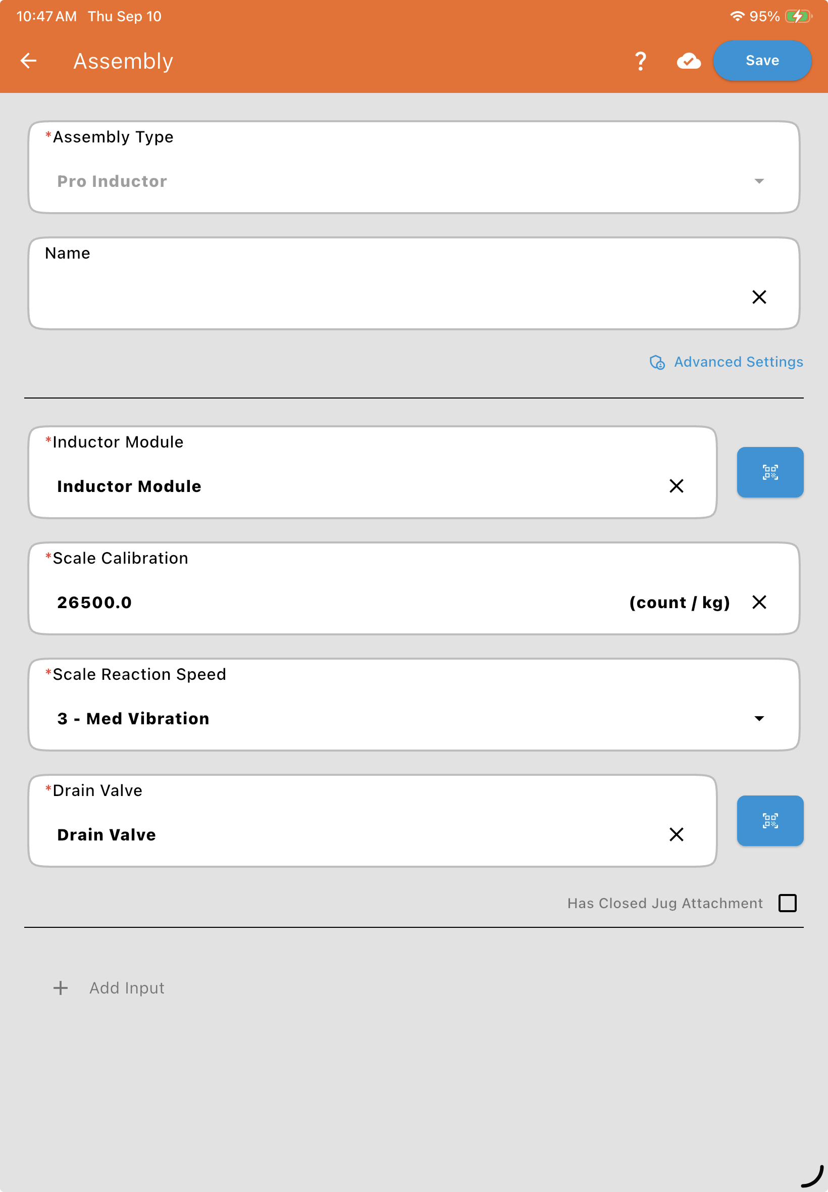
Inductor Module: The P/P Inductor Module mounted inside the Pro Inductor frame. It reads the load cells and controls all inductor-specific valves.
Scale Calibration: Converts raw load cell data into kilograms.
Scale Reaction Speed: Sets sensitivity to environmental factors (wind/vibration). 3-Med Vibration works for most conditions. 1-Min Vibration is used for very stable environments.
Drain Valve: Defines the valve used to drain the inductor tank: a CAN bus valve, entered by its Valve Information (QR Code), which also holds the valve's serial number.
Additional Input Valves (Up to 5):
Plumbing Name: The name shown in the selection dropdown on the Mix Preview screen.
Throttle Valve: The control valve located under the hood of the Pro Inductor: a CAN bus valve, entered by its Valve Information (QR Code), which also holds the valve's serial number.
Hose Dimensions: The diameter and length of the hose for this input (required for the Charge Line feature). See Where do I enter hose dimensions for the inputs?.
Has Closed Jug Attachment: Toggle this on if this Pro Inductor has the Closed Jug attachment installed on the lid. This apparatus has its own dedicated jug rinse switch and jug rinse valve, letting an operator drain, measure, and rinse jugs in a fully closed system — required in some jurisdictions by regulation.
Advanced Settings
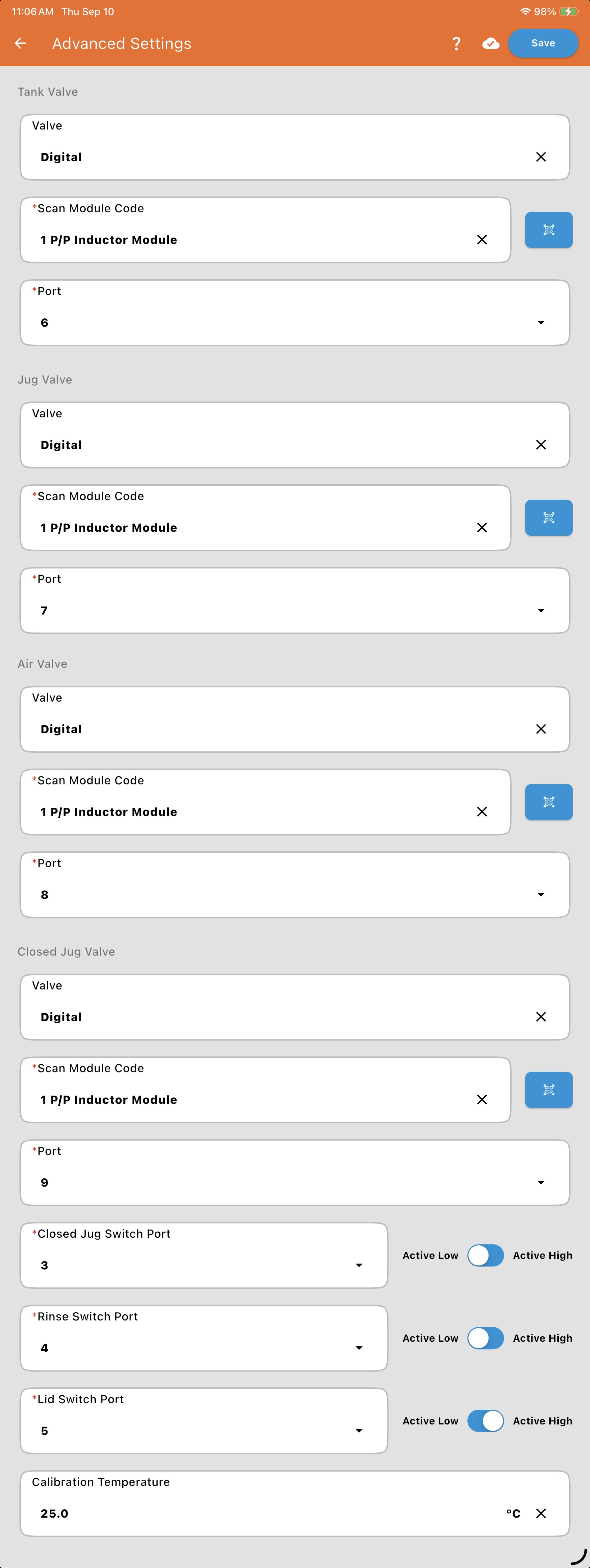
Section titled “Advanced Settings”Tap Advanced Settings to wire up the individual valves behind the settings above. Each valve below is entered with its Valve Type (Digital or CAN bus), then either its Wired To (a digital valve's module and port) or its Valve Information (QR Code) (a CAN bus valve), and its Serial Number. See Valve and Flowmeter Fields.
On the Pro, the ports are the Inductor Module's outputs and inputs shown in Pro Inductor Electrical. They are different from the Fusion's.
Tank Valve: Used to rinse the inductor tank with the specified amount entered for the product in work orders. Output 6.
Jug Valve: Controls the rinse used to clean out the jug the operator has placed on the jug rinse. Output 7.
Air Valve: Controls the air purge for the inductor. Output 8.
Rinse Switch Port: The input from the jug rinse sensor, the proximity sensor on the jug rinse arm that detects a jug pressed down. It isn't a manual switch, and the indicator light on it is the sensor's own light. Digital In 4, set to Active Low. This is the sensor's input, not the Jug Valve's output (Output 7): the two are separate entries. See Proximity Sensors.
Lid Switch Port: The input from the Pro Lid Sensor, the proximity sensor that detects whether the inductor lid is open or closed. Digital In 5, set to Active High.
Calibration Temperature: The temperature (°C) the scale was calibrated at.
Per-Input Wiring: Each of the Additional Input Valves listed above (input 1, input 2, etc.) also has its own Valve/Module/Port entry here.
If Has Closed Jug Attachment is on, a Closed Jug Valve section also appears here, with its own Valve/Module/Port, plus a Closed Jug Switch Port (with Active Low/Active High polarity) for the attachment's dedicated jug rinse switch and valve. Note: The Rinse Switch Port above is not used for the Closed Jug attachment.
If the jug rinse works in Diagnostics Mode but not when a jug is pressed down, don't change these ports or the polarity to work around it. See Inductor/Scales (Jug Rinse).