Inductor/Scales
Expand whichever matches what you’re seeing to figure out which component is having the problem and how to test it.
Which Component Is Having the Problem?
Section titled “Which Component Is Having the Problem?”Scale — not reading, draining, or weighing correctly
Step 1: Start in Diagnostics Mode
Whatever the specific symptom, the first thing to do with a scale is a baseline check in Diagnostics Mode (Manual Mode tab > select your machine > Diagnostics Mode tab > Inductor Scale card).
- Empty reading: With the inductor completely empty, the weight should read slightly negative — not exactly zero. That's normal.
- Responsiveness: Press down on the inductor with your hand. The weight should move as expected in response. If it doesn't move at all, you likely have a wiring or hardware problem — see Step 2 below.
- Erratic or incorrect weight? Unplug one load cell at a time at the module (see the two round, threaded connectors described in Step 2) and watch whether the behavior improves or gets worse. If unplugging one load cell improves the reading, that load cell is likely damaged. You can leave it unplugged and run temporarily on the single remaining load cell — but if you do, run the Calibrate Scale Wizard and Set Scale Empty Weight Wizard again before measuring product, since removing a load cell changes the scale's weight distribution. See Step 8 to replace the damaged load cell's connector when you're ready.
Step 2: Scale Not Reading Anything At All?
If the inductor weight stays at zero or doesn't respond when you add product, there are two likely causes: an uninitialized software setting, or a physical break in the communication line.
- Check the Scale Empty Weight setting. The most common software cause is an uninitialized Scale Empty Weight — if the system doesn't know the baseline weight of the empty plumbing, it may fail to display a live reading. Run the Set Scale Empty Weight procedure again to re-sync the system.
- Inspect the wiring. If that doesn't fix it, you likely have a physical disconnect. Load cell wires are thin and are common targets for vibration wear or rodents.
- Access the module: Fusion Inductors — open the back access panel. Pro Inductors — open the top access cover.
- Locate the module with two round, threaded connectors.
- Check the connectors: ensure threaded collars are tight, then unplug and inspect the pins for corrosion or "greening."
- Trace the wires for loose connections, breaks, frays, or rodent damage from off-season storage. If you find cut or chewed wire, see Step 8 — as long as enough undamaged wire remains to reach the module, you can repair it by fitting a new connector rather than replacing the whole load cell.
- Verify in Diagnostics Mode. Go to Diagnostics Mode (Manual Mode tab > select your machine > Diagnostics Mode tab), find the Inductor Scale card, and toggle the reading ON. Press down on the inductor tank with your hand — if the numbers move even slightly, the wiring is intact and you likely just need to calibrate (Step 4).
Step 3: Inductor Not Draining?
Check these in order:
- Are you getting weight readings in Manual Mode? See Manual Mode.
Has the Scale Empty Weight been properly set? See Set Scale Empty Weight Wizard.
This is the opposite failure mode of Error 202 (which doesn't get thrown here): if something added extra weight while the wizard was capturing its baseline — see Common Mistakes That Throw Off the Result — later readings will look artificially light, and the system can think the inductor is already at or below target weight even while it's still full of product. It never opens the drain valve at all when you press Done. Re-running the wizard correctly fixes the target weight and lets the drain trigger normally.
- Does the drain valve move in Manual Mode?
- Are you getting a 301 error message in Manual Mode for the drain valve? This means your tablet configuration doesn't match the modules the machine is seeing — make sure the serial number in the tablet matches the drain valve serial number. Check this at Data > Mixmates > Assemblies > Inductor > Drain Valve.
Step 4: Readings Inaccurate? Calibrate the Scale
If you notice inductor weights are consistently off, or you just replaced a load cell or connector, recalibrate the scale — see the Calibrate Scale Wizard for the Wizard and manual methods.
Step 5: A Specific Product Not Measuring Right? Adjust Density Instead
If a known container size pours in and shows the wrong volume, remember Mixmate calculates volume based on weight — a discrepancy usually means the product's density setting needs a small adjustment, not a full recalibration.
- Consistently off across all products? Recalibrate the physical scale (see Step 4) using a 5-gallon measuring vessel of water.
- Only one product reads wrong (most common)? Adjust that product's Density (lb/gal) in the app using the percentage the reading is off.

Example: You poured a 2.5 gallon jug. Mixmate showed 2.35 gallons. Your current density setting is 8.35 lb/gal. (2.35 / 2.5) × 8.35 = 7.849. Update that product's density to 7.849 in Data > Products — the next jug will match.
Step 6: Dry Products Look Less Stable Than Liquids?
This is expected — it comes down to the resolution of the load cells and how our brains perceive different units. Fusion Inductor resolution is 0.125 lbs; Pro Inductor is 0.05 lbs. Liquids display in Gallons, so a tiny weight change is a tiny fraction of a gallon. Dry products often display in Pounds, where that same weight change looks much larger.
| 0.01 Gallons of Water equals... | Equivalent Measurement |
| In Dry Ounces | 1.34 oz |
| In Pounds | 0.084 lbs |
| In Grams | 38.1 g |
Because the system can detect as little as 0.05 lbs (Pro), a gust of wind, pump vibration, or how a dry product settles in the cone can flicker the readout between increments. If your dry weights bounce excessively: check for wind catching the inductor lid, check for vibration from a pump or engine, and make sure no hoses or wires are hanging on and pulling at the scale assembly.
Step 7: Seeing Error 203 (Weight Not Settling)?
Error 203 is thrown because the inductor weight isn't becoming steady — usually due to a high-vibration environment. To check: look at the tablet screen while it's in the tablet holder. If you can't see a clear reflection of yourself, you're dealing with vibration.
Consider adding vibration isolation to your pump mounts — this is the McMaster-Carr option we use.
You can also fix this in software by adjusting Scale Reaction Speed, which determines how the Mixmate filters out vibration — from pumps, engines, or wind — while measuring the weight in the inductor. Only adjust this if a scale that was working properly at installation starts giving unstable readings; it isn't a setting to tune otherwise.
- Higher Sensitivity (Fast Reaction): The scale responds instantly to weight changes — great for accuracy when the system is still, but it can lead to erratic readings if there's any vibration.
- Lower Sensitivity (Slow Reaction): The system "smooths" the data, averaging the weight over a split second to ignore the pump's "chatter" and give a stable number for the automated valves to work with.
To adjust it:
- Open the Data tab, tap Mixmates.
- Tap the three dots on your Mixmate's card, tap Configuration, then accept the warning.
- Open the Assemblies tab, tap the middle of the Inductor assembly.
- Locate Scale Reaction Speed near the top/middle of the screen, just under the Inductor module listing.
- Lower it to make the scale less sensitive if the weight is flickering or jumping around, then tap Save in the upper right.
- Tap the System tab and Save once more to send the update to the hardware.
If lowering the reaction speed doesn't resolve it, the instability may be coming from a failing load cell rather than vibration — see the load cell isolation check in Step 1.
Step 8: Load Cell or Connector Damaged? Replace It
If you've identified a bad load cell — whether from corrosion/damage you can see, or from the isolation check in Step 1 — there are two possible fixes: replace just the connector, or replace the entire load cell. Which one you need depends on where the actual damage is: if the connector itself is corroded or physically damaged but the load cell is otherwise fine, replacing the connector is enough. This also covers a cut or rodent-damaged wire — as long as there's enough undamaged wire left, after trimming back to good copper, to fit the new connector and still reach the module. If the load cell itself has failed (not just its connector or wire), the whole unit needs to be replaced instead.
Option 1: Replace the Connector (Including Cut or Rodent-Damaged Wire)
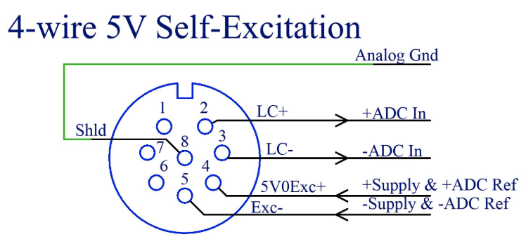
- Prepare the wire: Cut the wire away from the old connector, cutting back far enough to remove all existing heat shrink and any corroded copper.
- Disassemble the new connector: Place the thick seal into the rear part of the connector housing.
- Slide the housing onto the wire, pushing it back out of the way while you work the individual strands.
- Strip the outer jacket about 1 inch (25 mm) to expose the internal wires, then strip each small wire about 1/8 inch (3 mm).
- Fold-back technique: Fold the exposed copper back over its own insulation — this gives the terminal screw a thicker surface to bite into for a reliable, vibration-resistant connection.
- Wire to pins: Pin 8 — Bare Wire (Shield), Pin 2 — White Wire, Pin 3 — Red Wire, Pin 4 — Green Wire, Pin 5 — Black Wire.
- Final assembly: Slide the housing back up to the terminal block and screw the connector together, tightening the rear seal to keep moisture out.
Watch the video below for a visual walkthrough:
Option 2: Replace the Entire Load Cell
- Unbolt the old load cell and remove it.
- Remove the old wire, disconnecting it from the module.
- Route the new wire along the same path the old wire took.
- Bolt in the new load cell.
Once the repair is complete — whether you replaced the connector or the whole load cell — run the Set Scale Empty Weight Wizard along with the Calibrate Scale Wizard (see also Step 4) before measuring product again.
Good to Know: Why We Set a Minimum Water Level When Draining
The goal of a perfect inductor cycle is to drain the product and rinse water without ever "sucking air." Maintaining a specific water level at the end of the drain matters for two reasons:
- Preventing pump airlock: If the inductor drains too low, a large gulp of air enters the suction line. If that air pocket reaches your centrifugal carrier pump, it can airlock — the pump loses prime and stops moving fluid, often requiring you to stop the engine, bleed the pump housing, and re-prime.
- Eliminating foam: Introducing air into the hose to your sprayer tank increases the chance of foaming. Keeping a solid "plug" of liquid in the line keeps the mix stable and prevents the sprayer tank from overflowing with foam.
This is configured with a dedicated wizard in the Manual Mode tab — see the Set Scale Empty Weight Wizard.
Jug Rinse — not activating, or spraying on its own
If your jug rinse nozzle starts spraying without a jug being pressed down, it is usually a sign that the jug rinse sensor inside the inductor is failing or providing a "false positive" signal.
Why Sensors Fail
The jug rinse sensor is located in the "heart" of the inductor, where it is exposed to high-pressure water and a wide variety of concentrated chemicals.
Chemical Exposure: While we use high-quality, chemical-resistant components, some aggressive products can eventually work their way past the seals over time.
The Result: If moisture or chemical residue gets inside the sensor housing, it can create an internal short that makes the system "think" a jug is being held down, triggering the rinse cycle unexpectedly.
How to Fix It
Because this is a hardware issue, the sensor typically needs to be replaced to restore reliable operation.
Temporary Workaround: If you are in the middle of a field, you may need to manually close the water supply valve to the inductor rinse to prevent it from spraying until the sensor can be replaced.
Permanent Fix: Follow the link below for a step-by-step guide on how to swap out the old sensor for a new one.
Technical Guide: Proximity Sensors
Tank Rinse — seeing chemicals in the inductor rinse
If you notice chemical residue or "backflow" in the inductor rinse area during a wash cycle, it indicates a pressure imbalance. Instead of the rinse water clearing the lines, the chemical is likely being pushed back or failing to be drawn out.
Understanding the Cause
Typically, the chemical showing up in the inductor rinse is actually coming from a Stack's rinse line, not the inductor's own plumbing. The rinse line tees off the main carrier line between the flowmeter and the carrier valve, then tees again to split between the rinse pump that supplies the inductor and the pump that supplies the stack rinses.
If the main carrier valve is open too wide, it doesn't create enough pressure differential in the main line. If the main pump isn't pulling hard enough on the stack rinse side while the inductor rinse is running at the same time, chemical can travel backwards through the rinse lines and end up in the inductor instead of flushing out through the stack.
Assuming your plumbing is installed correctly, this same lack-of-suction / excess-back-pressure imbalance is the underlying cause in general — for the rinse to work effectively, the main carrier stream must create enough vacuum to pull the rinse water and chemical remnants through the system in the intended direction.
Potential Issues to Check:
Blockage in the Main Carrier Line: Check the main hose leading from the Mixmate to the sprayer/destination tank. A kinked hose, a clogged inline filter, or debris in the line will create back-pressure, preventing the inductor from draining properly.
Main Pump Issues: If your main pump is not reaching its optimal RPM or if the impeller is worn, it may not be generating the high-velocity flow required to create a vacuum at the inductor.
Closed or Partially Closed Valves: Trace the line from the Mixmate all the way to the destination tank. Ensure every manual valve is fully open. A valve that is only halfway open can create enough restriction to stall the induction process, causing chemicals to "sit" or back up into the rinse stream.
Inductor Drain Obstruction: Check for any "slugs" of thick, un-agitated chemical or debris (like jug seals) that might be partially blocking the drain at the bottom of the inductor.
Pro-Tip: The "Carrier Valve" Check
As explained above, an over-open carrier valve is the usual root cause. Throttling the carrier valve slightly increases the vacuum on the inductor side, which helps ensure the rinse cycle "scavenges" all remaining chemicals out of the tank instead of letting them travel backward into the inductor. See Partial Valve Position for how to adjust it.
Continuous Flow — not working as expected
If you find that the Continuous Flow button is greyed out or inactive, it is usually because the system is missing a specific piece of data for that product: the Container Size.
The Solution: Setting Container Size
The Mixmate system needs to know the volume of the source container to enable continuous flow features. Follow these steps to activate the button:
Navigate to the Data tab on your tablet.
Select Products.
Select the product you are trying to use.
Enter a value in the Container Size field and select the appropriate Unit of Measure (e.g., 2.5 Gallons, 250 Gallon Tote).
Press Save.
Why does this matter?
The Continuous Flow button relies on knowing how much product is available in a single "unit" to help track inventory and manage the flow properly. Once the system has a reference point for the container size, the button will become active, allowing you to proceed with your mix.
Why Does the Tank Rinse Valve Shut While in Continuous Flow?
This is expected behavior, not a malfunction. It means the inductor's scale has hit its maximum capacity — the system closes the tank rinse valve to stop more water coming in and prevent the inductor from overflowing.
The drain valve is still open the whole time. The real issue is that the main pump isn't emptying the inductor as quickly as the rinse water is flowing into it, so weight keeps climbing until the system has to cut off the incoming rinse water to keep up.