Proximity Sensors
The inductor uses proximity sensors to detect a jug pressed against the jug rinse arm, or the lid closing on a Pro Inductor. If one of these is activating on its own or failing to trigger, the sensor itself usually needs replacement.
Removal and Installation
The steps and gap setting are the same for either sensor — a jug rinse sensor and a Pro Lid Sensor are the same concept and use the same wrench size, just mounted in different locations on the inductor.
Remove the Old Sensor: Use a 15/16 inch wrench to unscrew the sensor from its mount (the jug rinse arm, or the lid bracket for a Pro Lid Sensor).
Install the New Sensor: Thread the new sensor in.
The Gap: Leave approximately a 1/16 inch (1 mm) gap between the tip of the sensor and the target it detects (the lever, or the lid).
Wire Orientation: Aim the wire along the tube while tightening to prevent it from getting pinched or snagged.
Route the Wire: Follow the same path as the old wire back to the module. Replace any zip ties you removed during the process to keep the cabling secure.
Wiring the Connector
This process requires a small flatblade screwdriver and patience to ensure the pins are seated correctly.
Unplug the Connector: Remove the connector from the module to work on it more easily.
Remove the Wedge: Locate the brightly colored "wedge" on the face of the connector (the part that plugs into the module). Gently pry this out with your screwdriver.
Depin the Old Wires: Work one wire at a time to avoid confusion.
Insert the screwdriver to hold the internal pin latch toward the center of the connector.
Simultaneously pull the wire out from the back of the connector.
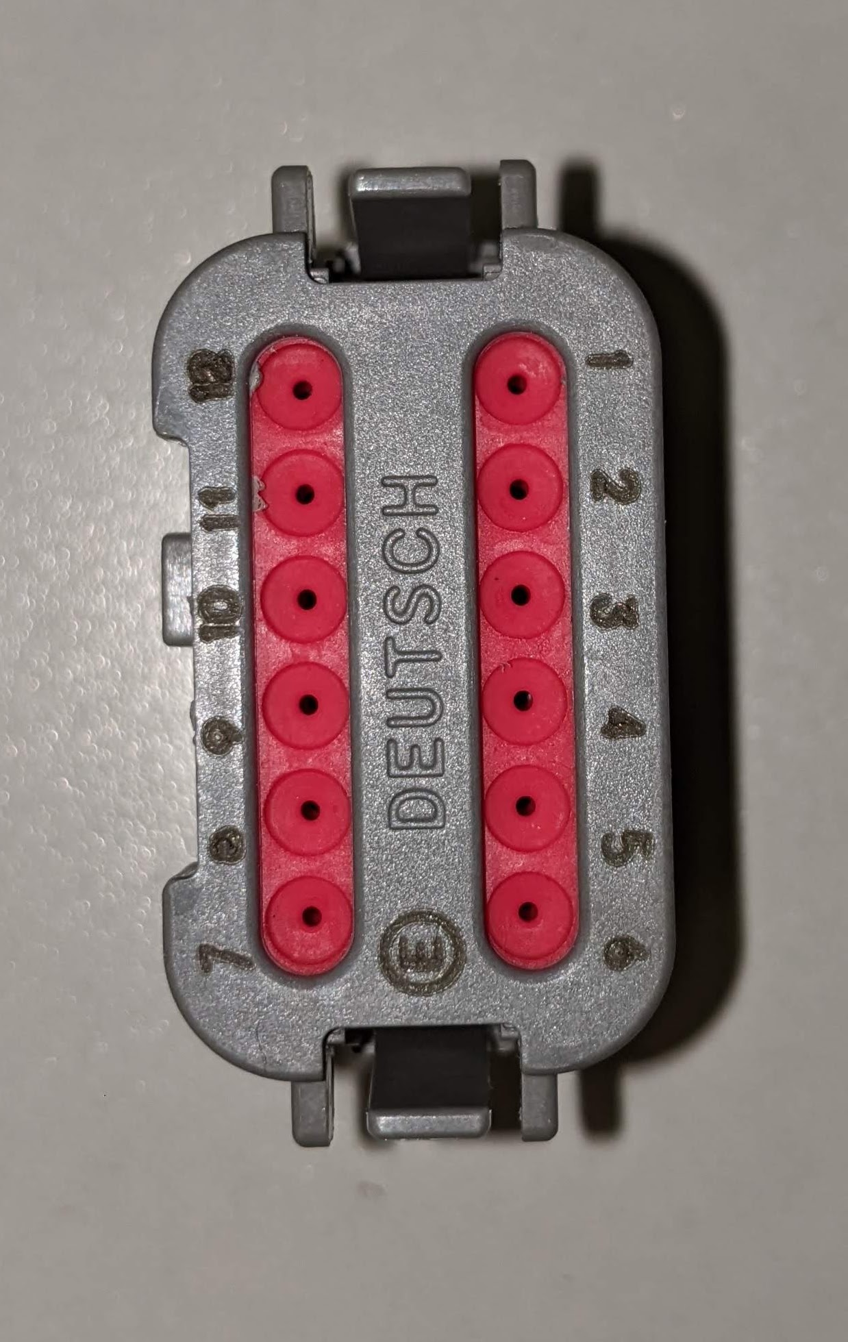
Insert New Wires: Push the new pins into the correct slots (see pinouts below) until they click.
Reassemble: Once all wires are swapped, snap the wedge back into the connector and plug it into the module.
Wiring Pinouts by Sensor
Verify which sensor and inductor model you have before pinning the connector — incorrect wiring can damage the sensor or the module.
Fusion Rinse Sensor:
Blue - Pin#5 - Ground
Brown - Pin#6 - 12 V+
Black - Pin#8 - Signal
Pro Rinse Sensor:
Blue - Pin#4 - Ground
Brown - Pin#7 - 12 V+
Black - Pin#9 - Signal
Pro Lid Sensor:
Blue - Pin#5 - Ground
Brown - Pin#6 - 12 V+
Black - Pin#8 - Signal
Verification
Once installed, enter Diagnostics Mode (Manual Mode tab > select your machine > Diagnostics Mode tab). Manually trigger the sensor — depress the jug rinse lever, or close the lid for a Pro Lid Sensor — and confirm the status on the screen toggles to show the sensor is triggered.
Instructional Video
For a visual guide on depinning the connector and setting the sensor gap on a jug rinse sensor, watch here: