Fusion Inductor Electrical
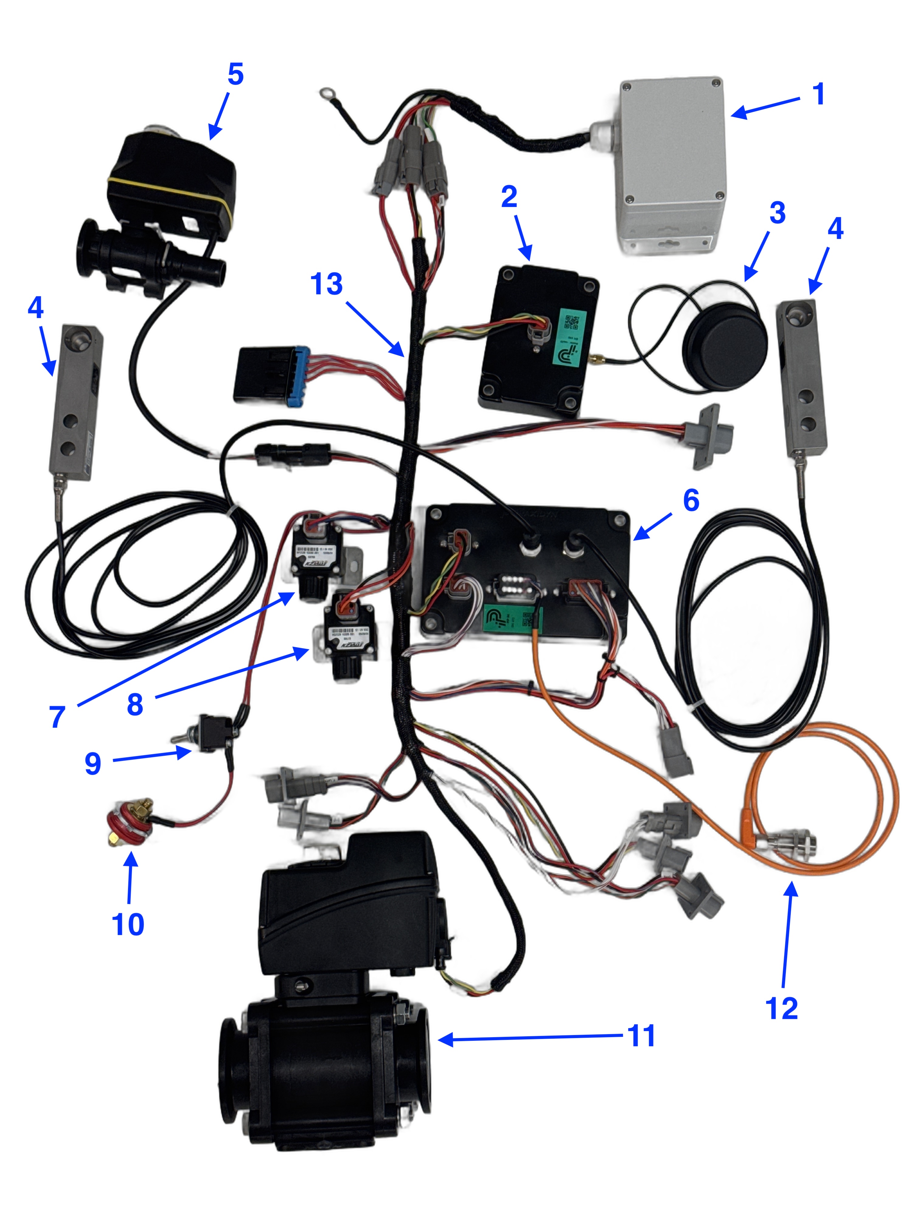
| Item | Part Number | Part Name |
|---|---|---|
| 1 | E0000082 | Power Module |
| 2 | E0000010 | Master Module |
| 3 | E0000051 | Wifi Antenna |
| 4 | A0000029 | Load Cells |
| 5 | A0000061 | Tank Rinse Valve |
| 6 | E0000092 | Inductor Module |
| 7 | A0000060 | Jug Rinse Valve |
| 8 | A0000059 | Air Valve |
| 9 | V0000388 | Power Switch |
| 10 | V0000057 | Panel Mount Power Post |
| 11 | V0000129 | Drain Valve |
| 12 | E0000132 | Rinse Sensor Package |
| 13 | E0000060 | Fusion Harness |
Installed in the Frame
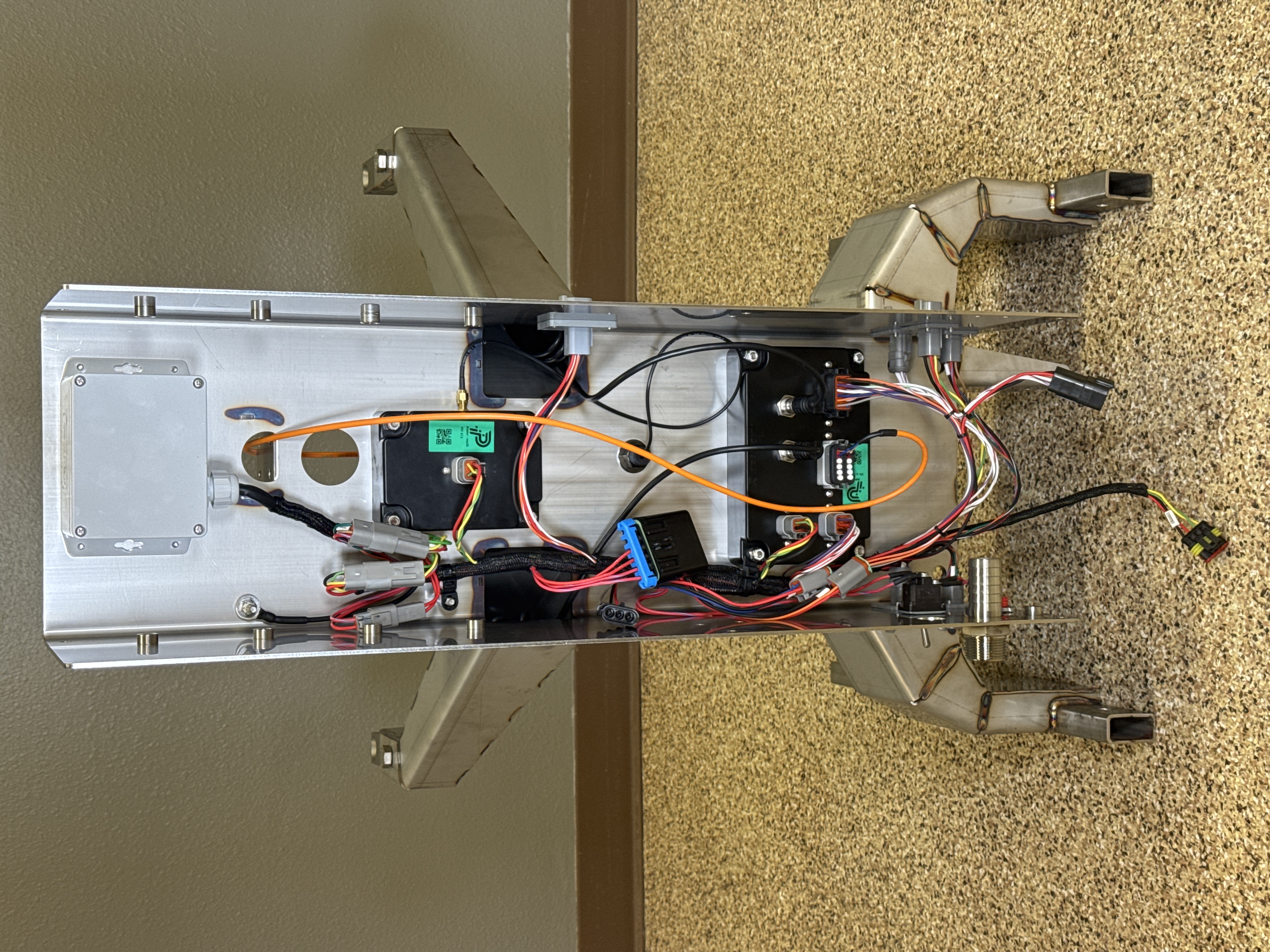
Section titled “Installed in the Frame”For reference, here is the same wiring installed in the Fusion Inductor frame:
Inductor Module Connector Pinouts
Section titled “Inductor Module Connector Pinouts”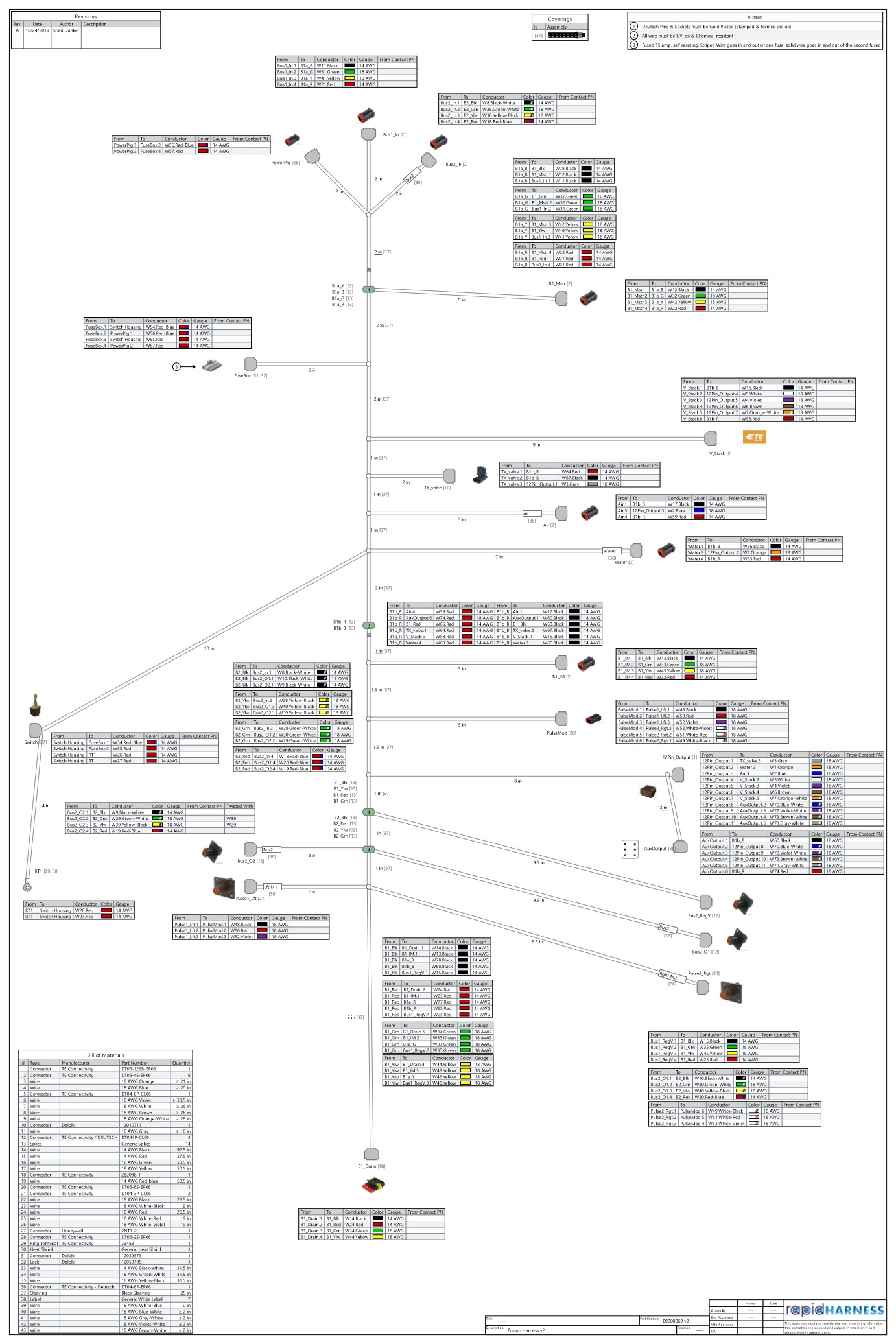
Inputs
Section titled “Inputs”6-pin Connector
Section titled “6-pin Connector”| Pin | Description |
|---|---|
| 1 | Ground |
| 2 | Power |
| 3 | Flowmeter 1 Signal |
| 4 | Flowmeter 2 Signal |
| 5 | Power |
| 6 | Ground |
Center Grey 12-pin Connector
Section titled “Center Grey 12-pin Connector”| Pin | Description |
|---|---|
| 1 | Ground |
| 2 | Ground |
| 3 | Ground |
| 4 | Ground |
| 5 | Ground |
| 6 | Power |
| 7 | Power |
| 8 | Digital In 5 - Jug Rinse Switch Signal |
| 9 | Digital In 4 |
| 10 | Digital In 3 |
| 11 | Digital In 2 |
| 12 | Digital In 1 |
Outputs
Section titled “Outputs”Black 12-pin Connector
Section titled “Black 12-pin Connector”| Pin | Description |
|---|---|
| 1 | Output 1 - Tank Valve |
| 2 | Output 2 - Jug Rinse Valve |
| 3 | Output 3 - Air Valve |
| 4 | Output 4 - Pin 2 of Product Valve connector on side of frame |
| 5 | Output 5 - Pin 3 of Product Valve connector on side of frame |
| 6 | Output 6 - Pin 4 of Product Valve connector on side of frame |
| 7 | Output 7 - Pin 5 of Product Valve connector on side of frame |
| 8 | Output 8 - Pin 2 of Auxiliary connector inside bottom of frame |
| 9 | Output 9 - Pin 3 of Auxiliary connector inside bottom of frame |
| 10 | Output 10 - Pin 4 of Auxiliary connector inside bottom of frame |
| 11 | Output 11 - Pin 5 of Auxiliary connector inside bottom of frame |
| 12 | Output 12 - Unused |
Left side Connectors
Section titled “Left side Connectors”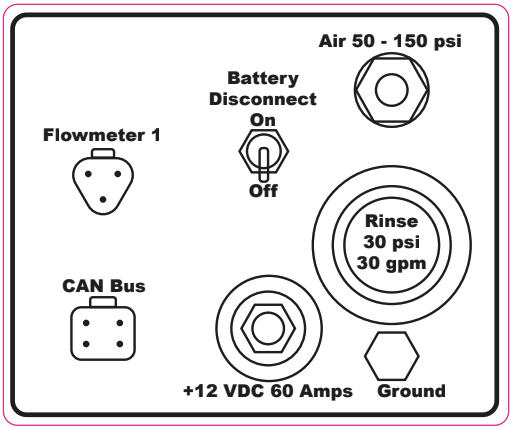
Flowmeter 1
Section titled “Flowmeter 1”| Pin | Description |
|---|---|
| A | Ground (Black) |
| B | Power (Red) |
| C | Signal (Blue or Green) |
CAN Bus
Section titled “CAN Bus”| Pin | Description |
|---|---|
| 1 | Ground (Black) |
| 2 | CAN Low (Green) |
| 3 | CAN High (Yellow or Orange) |
| 4 | Power (Red) |
Right side Connectors
Section titled “Right side Connectors”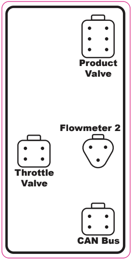
Product Valve
Section titled “Product Valve”| Pin | Description |
|---|---|
| 1 | Ground (Black) |
| 2 | Output 4 of Module |
| 3 | Output 5 of Module |
| 4 | Output 6 of Module |
| 5 | Output 7 of Module |
| 6 | Power (Red) |
Throttle Valve (for add-on stack usage)
Section titled “Throttle Valve (for add-on stack usage)”| Pin | Description |
|---|---|
| 1 | Ground (Black) |
| 2 | CAN Low (Green) |
| 3 | CAN High (Yellow or Orange) |
| 4 | Power (Red) |
Flowmeter 2
Section titled “Flowmeter 2”| Pin | Description |
|---|---|
| A | Ground (Black) |
| B | Power (Red) |
| C | Signal (Blue or Green) |
CAN Bus
Section titled “CAN Bus”| Pin | Description |
|---|---|
| 1 | Ground (Black) |
| 2 | CAN Low (Green) |
| 3 | CAN High (Yellow or Orange) |
| 4 | Power (Red) |