Fusion Inductor Assembly
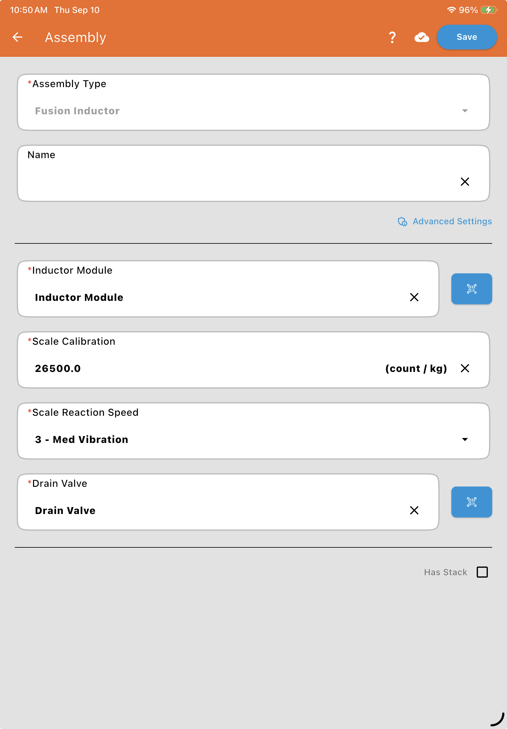
Inductor Module: The P/P Inductor Module mounted inside the Fusion Inductor frame.
Scale Calibration: Converts load cell data into kilograms.
Scale Reaction Speed: Adjusts for environmental noise (3-Med Vibration is standard).
Drain Valve: Defines the valve used to drain the inductor tank.
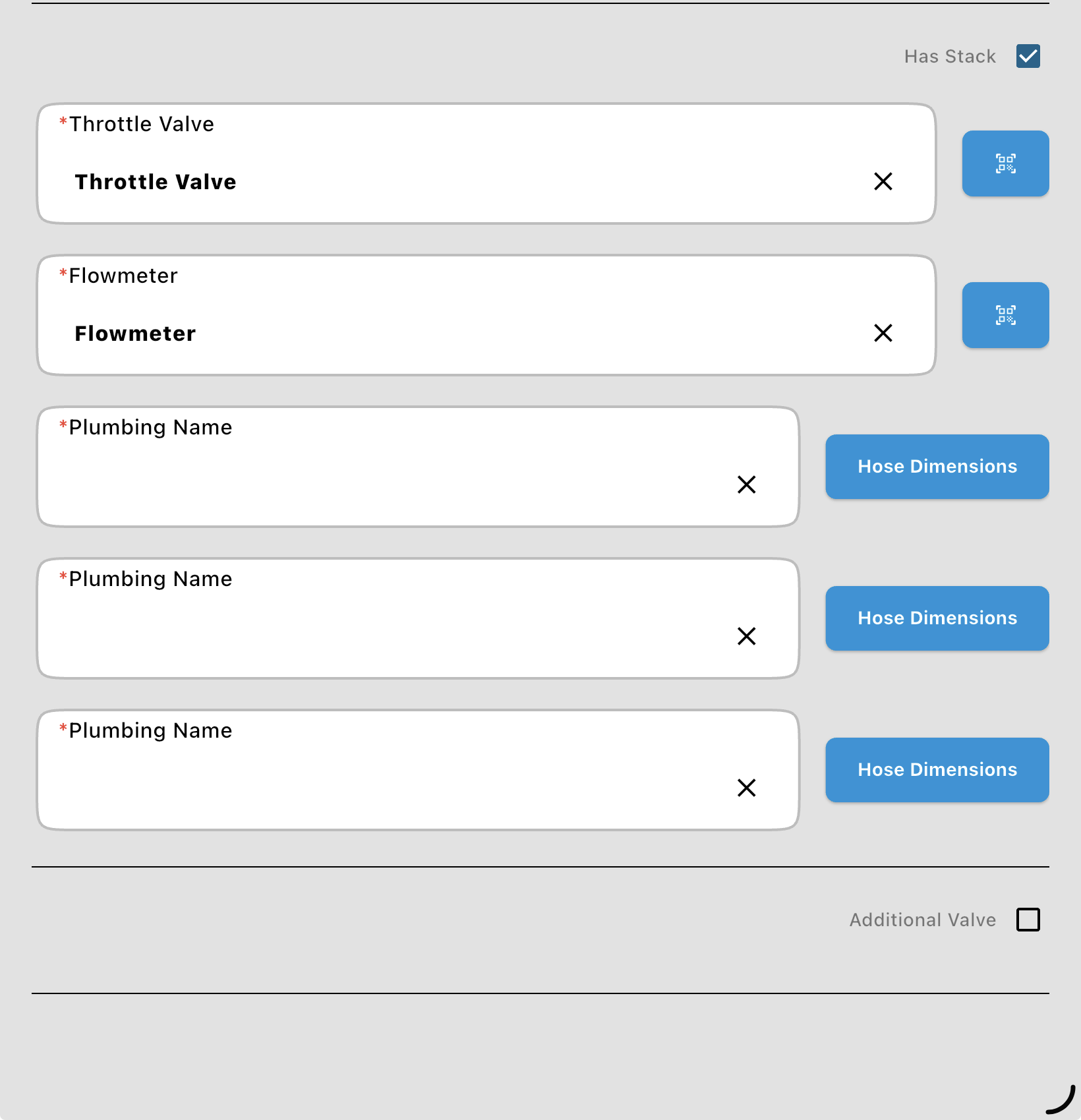
Has Stack Checkbox: Toggle this on if a stack is attached. This enables:
Stack Throttle Valve: The valve closest to the 3-inch tee on the main line.
Stack Flowmeter: Defined by serial number and calibration (counts per liter).
Stack Plumbing Inputs: Each input requires a Plumbing Name and Hose Dimensions. Inputs are numbered starting from the flowmeter and working away from it.
Additional Valve Checkbox: Used when a valve is added to the top of the stack. This becomes the Rinse Valve, and the valve below it becomes a plumbing input.
Advanced Settings
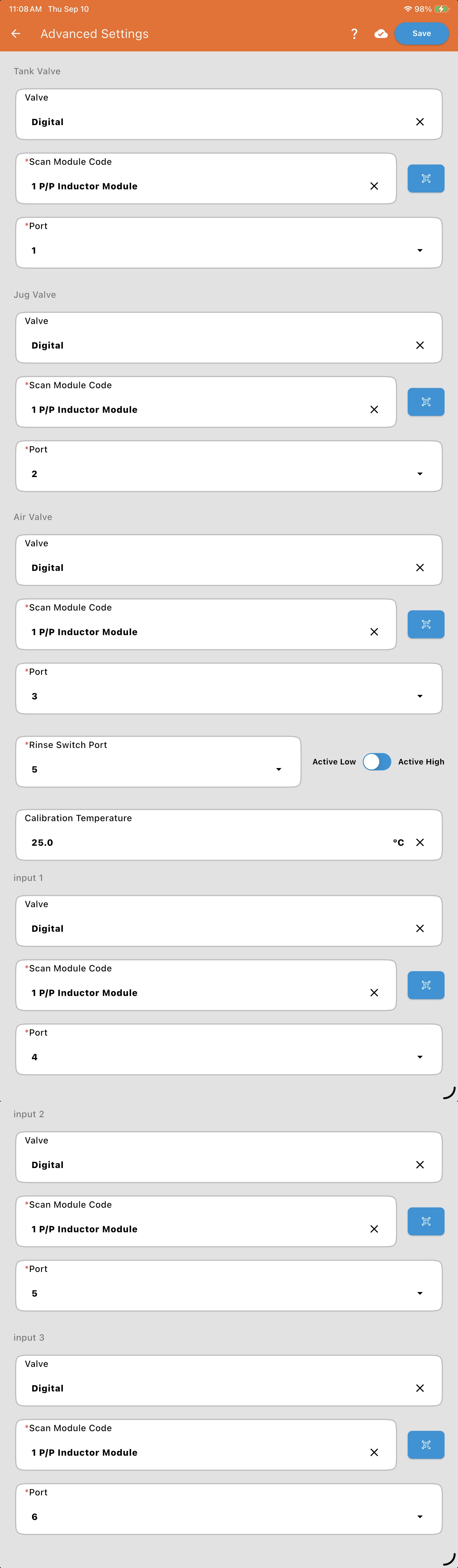
Section titled “Advanced Settings”Tap Advanced Settings to wire up the individual valves behind the settings above. Each entry below is defined by a Valve type (Digital or CAN bus), a Module (scanned or entered), and a Port:
Tank Valve: Used to rinse the inductor tank with the specified amount entered for the product in work orders.
Jug Valve: Controls the rinse used to clean out the jug the operator has placed on the jug rinse.
Air Valve: Controls the air purge for the inductor.
Rinse Switch Port: The switch the operator uses to trigger a rinse, with an Active Low/Active High polarity setting.
Calibration Temperature: The temperature (°C) the scale was calibrated at.
Per-Input Wiring: Each of the Additional Input Valves listed above (input 1, input 2, etc.) also has its own Valve/Module/Port entry here.